Simple. Economical. Reliable.
ADVANTAGES
- Many of the circuits involved can be shrunk to the size of a dime with current manufacturing techniques.
- The tape consists of basic, common elements: graphite and polyvinyl acetate. The typical ballast has toxic components and metals that are discarded to a landfill when the ballast dies.
- The bulb life is dramatically lengthened because the lamp is fired evenly by the electromagnetic field interaction. The so-called "kick start" and ignition that emanates from either end of the lamp is eliminated.
MICROBALLAST BROCHURE
Below is the current marketing and informational brochure for the Microballast, available for viewing or download.
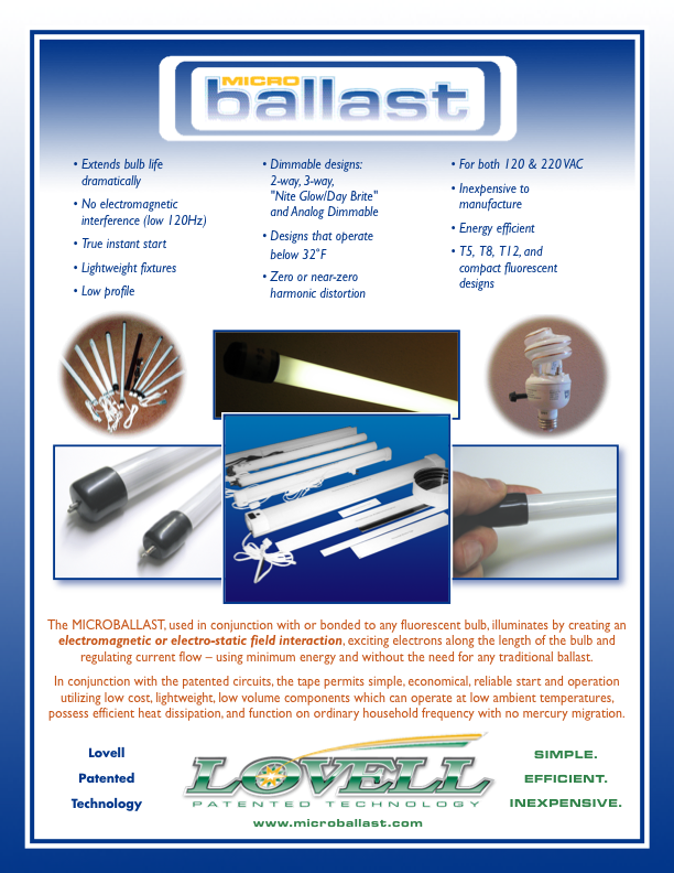


Click on the graphic to view a larger version.
CONSTRUCTION AND FUNCTION
The Microballast tape, used in conjunction with or bonded to any fluorescent bulb, illuminates by creating an electromagnetic or electrostatic field interaction, exciting electrons along the length of the bulb and regulating current flow – using minimum energy and without the need of any traditional ballast.In conjunction with the patented circuits, the tape permits simple, economical, reliable start and operation utilizing low cost, lightweight, low volume components which can operate at low ambient temperatures, possess efficient heat dissipation and function on ordinary household frequency with no mercury migration.
The inductive-resistive structure* consists of the tape and the medium temperature conductive-resistive coating interconnected between two elongated conductors (copper strips). The coating is comprised of a suspended conductive powder (graphite and china clay) and water situated in a polymer-based activator. The paint has a non-continuous electrically-conductive component (graphite particles) suspended in a substantially non-conductive binder (polyvinyl acetate). It is a solid emulsion – electrically conductive (graphite) discrete phase (separate particles) dispersed with non-conductive continuous phase (the polyvinyl acetate [PVA] flows continuously through the graphite particles). The emulsion may be located on a separate material like the tape or it may even be painted onto the bulb itself.
The Microballast tape also emits ohmic heat in response to the current passing through it. When the tape is placed in thermal communication with the bulb, a portion of this heat is transferred to the bulb housing, aiding in low temperature operation. This effect can be further enhanced by locating the tape on the bulb itself. And even with no heat transfer the Microballast functions more efficiently in low-temperature settings than conventional ballasts.
The Microballast can be located both on the bulb proper or in close proximity (1") and in some embodiments can be placed up to 12" away from the lamp. Once the lamp is illuminated by the tape, the tape can be removed and the lamp will remain illuminated.
* The term inductive-resistive structure is intended to refer to an electrical structure which is capable of inducing fluorescence in a fluorescent medium when an electric current is passed through the structure, while the structure is in proximity to the fluorescent medium, and while an electric potential is applied across the fluorescent medium. It is believed that the inductive-resistive structures in this invention work by means of an electromagnetic (e.g., magnetic and/or electrostatic) field interaction with the contents of the fluorescent bulb per se. The term inductive-resistive structure is NOT intended to refer to inductive reactances, transformer coils, etc., which may be found in a conventional ballast, and which do NOT exhibit the properties of this invention — an electromagnetic field interaction with the contents of the fluorescent bulb.